- Dynamic fatigue testing machine
- Friction and wear testing machine
- Fastener special testing machine
- Static mechanical property testing machine
- In-situ tensile testing machine
- Non-standard customized large and small mechanical equipment
- Metallographic sample preparation and analysis equipment
- hardmeter
- Solution of overall design and planning of laboratory
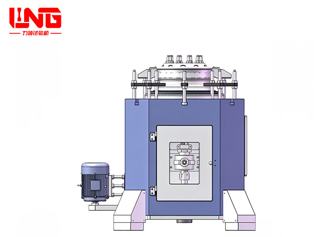
PQW-20000 Wheel rim rotary bending test bench
With the development of heavy load, light weight and long service life of trucks, construction machinery and rail transit vehicles, the fatigue reliability of wheels, as the key bearing and walking parts, directly determines the safety and operation and maintenance costs of the whole vehicle. Rim bears complex bending stress caused by the combined action of vehicle weight, cornering lateral force, road excitation and braking torque, and fatigue fracture has become one of the main modes of wheel failure.
Introduction
1.1 Project background
With the development of heavy load, light weight and long service life of trucks, construction machinery and rail transit vehicles, the fatigue reliability of wheels, as the key bearing and walking parts, directly determines the safety and operation and maintenance costs of the whole vehicle. Rim bears complex bending stress caused by the combined action of vehicle weight, cornering lateral force, road excitation and braking torque, and fatigue fracture has become one of the main modes of wheel failure.
The traditional wheel bending fatigue test mostly uses hydraulic actuator to carry out low-frequency pulsating loading, which has the limitations of low loading frequency (usually ≤5 Hz), small loading force, large equipment occupation and high energy consumption. The scheme of "centrifugal force loading of rotating weight" proposed in this scheme can generate constant amplitude alternating bending moment under high-speed rotation, and truly simulate the bending stress cycle of the rim when the vehicle is driving at high speed. More than 10 cycles can be completed in a single test, which significantly improves the test efficiency and scene restoration.
This equipment is mainly used for the type test, ex-factory inspection and fatigue life research of the truck wheel rim (12 "–26"). With the help of the two-component sensor and the laser displacement sensor, the bending moment response and bending deformation data of the wheel rim can be obtained synchronously, which provides a high-confidence test basis for wheel structure design, material selection and process optimization.
Parameters
|
serial number |
Parameter name |
index value |
remarks |
|
1 |
Maximum loading moment |
20 kN·m |
Adjustable 0.5–20 kn m |
|
2 |
Bending moment loading mode |
Centrifugal force of rotating weight |
m·r·L·ω² |
|
3 |
Speed range |
0–1500 r/min |
Continuously adjustable |
|
4 |
Main motor power |
≥ 7.5 kW |
Frequency conversion three-phase asynchronous motor |
|
5 |
Adapted rim specification |
16″–26″ |
Truck wheel rim |
|
6 |
Rim clamping mode |
T-groove chuck+center positioning |
Avoid scratching |
|
7 |
Bending moment measurement |
Bicomponent sensor |
|
|
8 |
Displacement measurement |
Laser displacement sensor ×2 |
Circumferential uniform distribution |
|
9 |
Number of test cycles |
≥ 1× 10 times |
Settable |
|
10 |
Total power of equipment |
≤ 10 kW |
Including control and assistance |
|
11 |
Overall dimension (L×W×H) |
About 3.2 × 2.0 × 2.4 m |
Including protective cover |
|
12 |
Total equipment mass |
About 3500 kg |
Including flywheel+weight |
|
13 |
the protection grades |
IP54 |
Electric cabinet |
|
14 |
Noise level |
≤ 78 dB(A) |
Station 1 m distance |
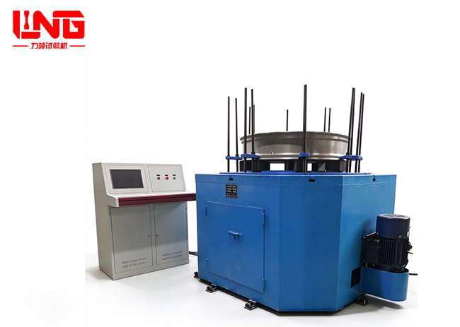
Fatigue of LPQW-50000 Wheel in Rotation and Bending testing machine
This testing machine is driven by variable frequency motor t...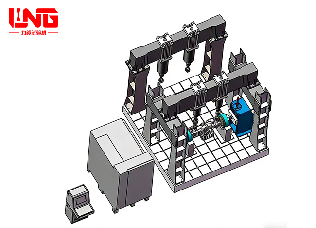
PWS-1000CQ comprehensive performance testing platform for drive axle housing
The comprehensive performance testing platform for the drive...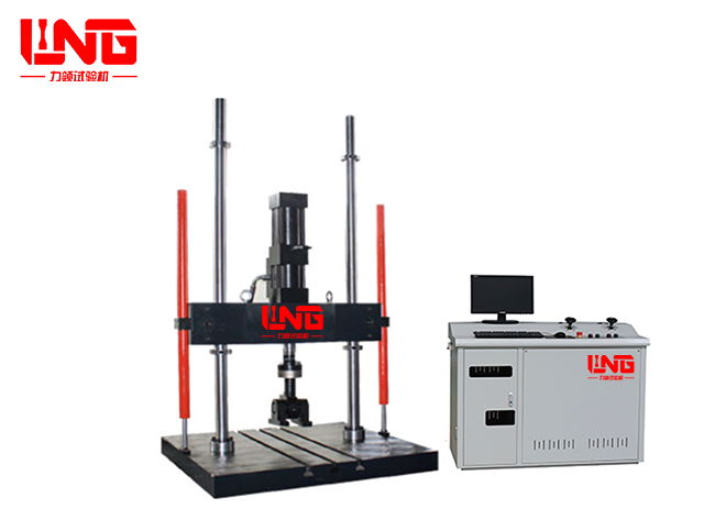
Electro-hydraulic servo channel fatigue testing machine
PWS-100 electro-hydraulic servo channel fatigue testing mach...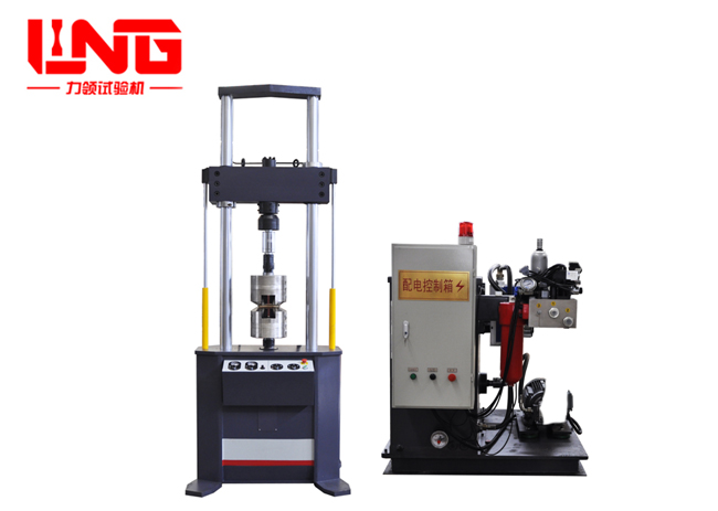
Electro-hydraulic servo dynamic and static universal testing machine
PWS series electro-hydraulic servo dynamic and static univer...
About LiLing
Product range
News
Contact LiLing
Address:Building 2, No. 6 Weihua West Road, Shizhong District, Jinan City, Shandong Province,China


Business consultation (WeChat)